Load balancing
Network Address Translation (NAT)
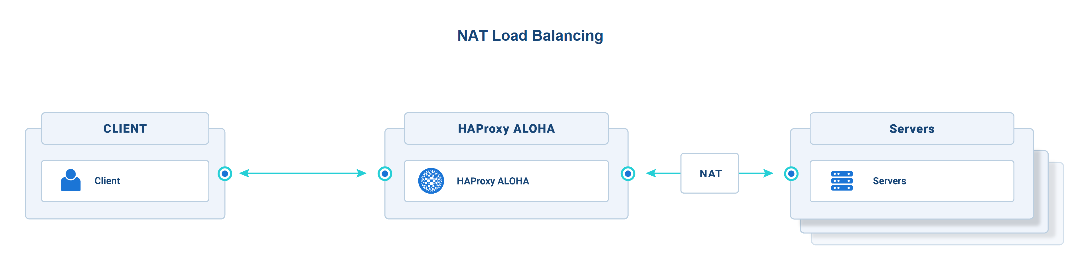
With Network Address Translation (NAT) enabled, the HAProxy ALOHA appliance can replace the source and destination IP addresses of incoming packets.
- Source NAT: The source IP of the incoming packet is replaced with the IP address of the HAProxy ALOHA appliance. Source NAT can be configured using the NAT tab, which translates the NAT rules into iptables rules.
- Destination NAT: The destination IP address is replaced with the private IP address of the backend server. Destination NAT can be configured using the NAT tab or, in applications using the LVS (Layer 4) load balancer, by specifying
nat modein the LVSdirectorconfiguration.
After the HAProxy ALOHA appliance translates the packet addresses, the changed packet is then sent to the backend server. When the HAProxy ALOHA appliance receives the server response, the original IP addresses are restored and the packet is sent back to the client.
Destination NAT allows a simpler configuration on the backend servers, which receive traffic on their private addresses, and simply return traffic to the source IP, which is that of the HAProxy ALOHA appliance.
NAT mode is supported by both Linux and Windows backend servers. Backend servers can keep the network’s external gateway as their default gateway. Disadvantages include that it reduces the number of connections that HAProxy ALOHA can support, due to needing to use more ports.
Optionally, instead of configuring source NAT (HAProxy ALOHA NAT tab), you can set HAProxy ALOHA to be the default gateway on the backend server. That accomplishes the same thing and would use fewer ports on HAProxy ALOHA, at the cost of a slightly more complex setup on the backend server (i.e. needing to change the default gateway).
NAT traffic flow Jump to heading
-
The client connects to your application at the configured public IP address (VIP). HAProxy ALOHA listens at that address and receives the packets.
-
The packet’s destination IP address is translated from the HAProxy ALOHA public IP to the private IP of one of the backend servers. Simultaneously, the packet’s source IP addresses are translated from the client’s IP to the HAProxy ALOHA IP address.
-
The backend server accepts the request to its IP.
-
The backend server sends its response to HAProxy ALOHA because its address is set as the source IP in the packet.
-
HAProxy ALOHA performs the reverse NAT before relaying the response to the client.
Important
NAT load balancing introduces:
-
a limit on the number of simultaneous connections to a backend server. Only 65534 source ports are available for HAProxy ALOHA addresses.
-
a heavy load on HAProxy ALOHA (connection tracking must be enabled).
NAT use case Jump to heading
NAT represents traditional Layer 4 load balancing, but it isn’t the only way to load balance Layer 4 protocols. From the LB Layer7 tab, you can load balance services over TCP via a reverse proxy configuration. This is the approach we recommend for TCP because it provides more detailed logging and is simpler to set up and troubleshoot. However, NAT enables you to load balance UDP services and to load balance services that utilize dynamic TCP ports, such as FTP.
For pure TCP service, use the LB Layer7 load balancer in tcp mode instead.
Configuring NAT Jump to heading
Configuring NAT involves these tasks:
- Enable destination NAT in the LVS
directorconfiguration. - Enable source NAT using a NAT rule.
- Enable connection tracking in the LVS service.
Enable Destination NAT Jump to heading
Configure LVS so that it translates the destination IP from the public IP on which HAProxy ALOHA listens to the backend server’s private IP.
-
In the web UI’s LB Layer4 tab, add the
mode natdirective to your existing configuration.In the example below, we load balance the UDP protocol.
haproxydirector web 10.0.0.3:8000 UDPbalance leastconnmode natserver web1 10.0.0.20:8000 weight 10 checkhaproxydirector web 10.0.0.3:8000 UDPbalance leastconnmode natserver web1 10.0.0.20:8000 weight 10 check -
Click OK and Apply.
-
Click on the Setup tab. In the Configuration section, click Save.
Enable Source NAT Jump to heading
Create iptables NAT rules to translate the client’s source IP to the HAProxy ALOHA appliance’s IP.
-
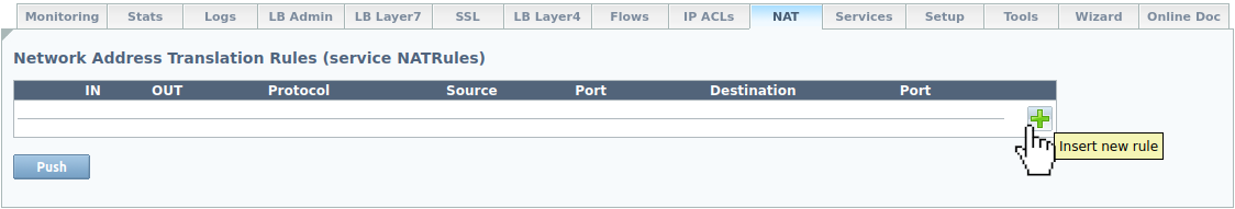
In the NAT tab, click Insert to add a new NAT rule.
-
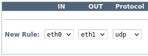
Select the following values in the New Rule area, depending on how many network interfaces are attached to HAProxy ALOHA.
-
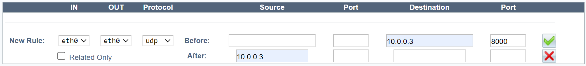
One network interface
text--------+-------- 192.168.1.0/24, VIPs, backend servers|| eth0+---------+| || ALOHA || |+---------+text--------+-------- 192.168.1.0/24, VIPs, backend servers|| eth0+---------+| || ALOHA || |+---------+Field Description IN Inbound network interface. OUT Outbound network interface, the same as the inbound interface. Protocol UDP Example:

-
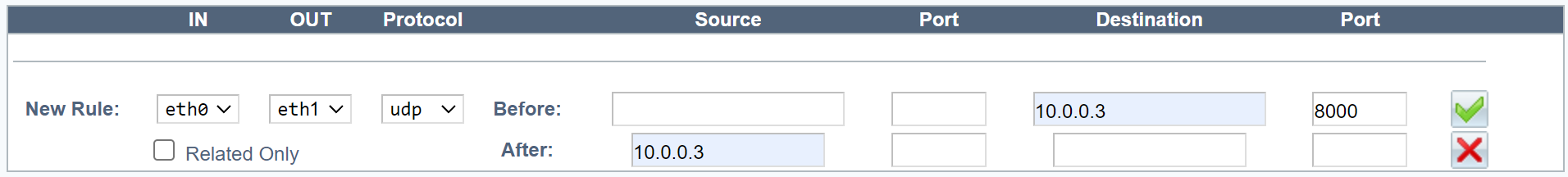
Two network interfaces
text--------+-------- 192.168.1.0/24, VIPs|| eth0+---------+| || ALOHA || |+---------+| eth1|--------+-------- 192.168.2.0/24, backend serverstext--------+-------- 192.168.1.0/24, VIPs|| eth0+---------+| || ALOHA || |+---------+| eth1|--------+-------- 192.168.2.0/24, backend serversInfo
In configurations having two network interfaces, if you have failover configured on one VIP, configure a VIP with failover on the other interface as well.
Field Description IN Inbound network interface. OUT Outbound network interface, different from the inbound interface. Protocol UDP. Example:
-
-
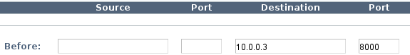
Enter the following values in the Before area.
Field Value Example Source Blank Source port Blank Destination VIP address 10.0.0.3 Destination port UDP port or range 8000, or 50000-51000 Example:
-
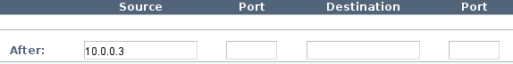
Enter the following values in the After area.
Field Value Example Source VIP address (Note: If you enter a local IP address, it can not be shared between the members of a cluster.) 10.0.0.3 Source port Blank Destination Blank Destination port Blank Example:
-
Check your configuration.
Example:
One network interface.
Example:
Two network interfaces.
-
Click Add and Apply.
-
Click on the Setup tab. In the Configuration section, click Save.
Enable LVS connection tracking Jump to heading
NAT relies on the connection tracking information so that it can translate all of the packets in a session in the same way.
-
Click the Services tab.
-
Locate the
lvsservice and click Setup. -
Enable connection tracking through the
conntrackkeyword.textservice lvs############ Linux Virtual Server, layer 3/4 load balancingconntracktextservice lvs############ Linux Virtual Server, layer 3/4 load balancingconntrack -
Click OK and then Close.
-
Locate the
lvsservice and click Restart. -
Click on the Setup tab. In the Configuration section, click Save.
Display NAT rules results Jump to heading
NAT rules are stored in the /etc/natrules/natrules.cfg file.
In the natrules.cfg entry below, TCP packets targeted for 172.30.100.0:3389 have their source IP address changed to 10.11.100.20 and are sent to device eth1.
natrules.cfgtext
natrules.cfgtext
To display the results of NAT rules, use this command:
nix
nix
Example output from preceding example natrules.cfg entry:
outputtext
outputtext
Do you have any suggestions on how we can improve the content of this page?