Layer 4 (LVS)
Load balance FTP (active mode) using the LB Layer4 tab
In active mode FTP, the FTP server responds to client requests by initiating a connection back to the client.
Important
Active FTP is not recommended because it fails when the FTP client is protected by a NAT router or firewall, which prevents the FTP server from establishing the connection with the client. To ensure that FTP service can be provided for clients in such networks, use passive FTP instead. The passive FTP solution also provides superior logging than the one described on this page.
To load balance active FTP services, use a Linux Virtual Server (LVS) load balancer in NAT mode to perform the load balancing at layer 4. In this scenario, responses from servers flow through HAProxy ALOHA (that is, not Direct Server Return).
This configuration supports high availability.
Example network architecture Jump to heading
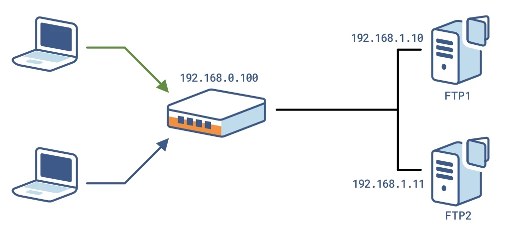
The procedures in this section are based on an example network architecture where clients access the FTP services at the load balancer IP address 192.168.0.100. The load balancer then directs traffic to FTP servers at 192.168.1.10 and 192.168.1.11.
Configure source NAT Jump to heading
Create a NAT rule to translate the client’s source IP to the HAProxy ALOHA appliance’s IP.
-
In the NAT tab, click Insert to add a new NAT rule.
-
The values you enter in the New Rule area depend on the number of network interfaces attached to HAProxy ALOHA.
-
One network interface
text--------+-------- 192.168.1.0/24, VIPs, backend servers|| eth0+---------+| || ALOHA || |+---------+text--------+-------- 192.168.1.0/24, VIPs, backend servers|| eth0+---------+| || ALOHA || |+---------+In a deployment with one network interface, select the following values in the New Rule area.
Field Description IN Inbound network interface OUT Outbound network interface, the same as the inbound interface Protocol TCP -
Two network interfaces
text--------+-------- 192.168.1.0/24, VIPs|| eth0+---------+| || ALOHA || |+---------+| eth1|--------+-------- 192.168.2.0/24, backend serverstext--------+-------- 192.168.1.0/24, VIPs|| eth0+---------+| || ALOHA || |+---------+| eth1|--------+-------- 192.168.2.0/24, backend serversInfo
In configurations having two network interfaces, if you have failover configured on one VIP, configure a VIP with failover on the other interface as well.
In a deployment with two network interfaces, select the following values in the New Rule area.
Field Description IN Inbound network interface OUT Outbound network interface, different from the inbound interface Protocol TCP
-
-
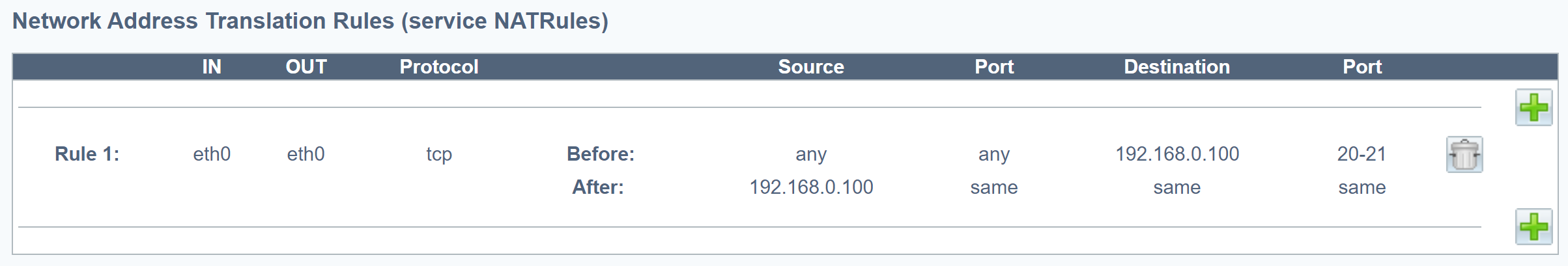
Enter the following values in the Before area.
Field Value Example Source Blank Source port Blank Destination VIP address 192.168.0.100 Destination port FTP port or range 20-21 -
Enter the following values in the After area.
Field Value Example Source VIP address (Note: If you enter a local IP address, it cannot be shared between the members of a cluster.) 192.168.0.100 Source port Blank Destination Blank Destination port Blank -
Check your configuration.
Example:
Rule for one network interface.
-
Click Add and Apply.
-
On the Setup tab, in the Configuration section, click Save.
Configure LVS load balancer and destination NAT Jump to heading
Define the LVS director d_ftp, which load balances the FTP traffic between the real FTP servers. LVS performs destination NAT.
-
Click the LB Layer4 tab.
-
Add this configuration:
haproxydirector d_ftpmode natbalance sourceoption icmpcheck interval 10server ftp1 <FTP real server 1 IP> weight 10 checkserver ftp2 <FTP real server 2 IP> weight 10 checkhaproxydirector d_ftpmode natbalance sourceoption icmpcheck interval 10server ftp1 <FTP real server 1 IP> weight 10 checkserver ftp2 <FTP real server 2 IP> weight 10 checkExample:
In the example, the FTP real servers are located at 192.168.1.10 and 192.168.1.11.
haproxydirector d_ftpmode natbalance sourceoption icmpcheck interval 10server ftp1 192.168.1.10 weight 10 checkserver ftp2 192.168.1.11 weight 10 checkhaproxydirector d_ftpmode natbalance sourceoption icmpcheck interval 10server ftp1 192.168.1.10 weight 10 checkserver ftp2 192.168.1.11 weight 10 check -
Click OK and then Apply.
-
Click on the Setup tab. In the Configuration section, click Save.
Configure a flow Jump to heading
Configure a flow that captures traffic sent to the VIP and sends it to the LVS director d_ftp:
-
Click the Flows tab.
-
Add this flow definition:
haproxyflow f_ftp director d_ftpmatch proto tcp dst <VIP> dstport 20:21haproxyflow f_ftp director d_ftpmatch proto tcp dst <VIP> dstport 20:21Example:
The example IP address for FTP access is 192.168.0.100.
haproxyflow f_ftp director d_ftpmatch proto tcp dst 192.168.0.100 dstport 20:21haproxyflow f_ftp director d_ftpmatch proto tcp dst 192.168.0.100 dstport 20:21Info
Make sure these ports are open on the FTP servers.
-
Click OK and then Apply.
-
Click on the Setup tab. In the Configuration section, click Save.
Configure the flow manager service Jump to heading
Configure the flow manager service for automatic startup:
-
On the Services tab, locate the flowmgr service and click Setup.
-
If the configuration contains the line
no autostart, delete the line. -
Click OK and then Close.
-
Locate the flowmgr service and click Restart.
-
Click on the Setup tab. In the Configuration section, click Save.
Configure the LVS service Jump to heading
Configure the LVS service for automatic startup and connection tracking. NAT relies on the connection tracking information so that it can translate all of the packets in a session in the same way.
-
On the Services tab, locate the lvs service and click Setup.
-
If the configuration contains the line
no autostart, delete the line. -
Enable connection tracking by adding the
conntrackkeyword.textservice lvs############ Linux Virtual Server, layer 3/4 load balancingconntracktextservice lvs############ Linux Virtual Server, layer 3/4 load balancingconntrack -
Click OK and then Close.
-
Locate the lvs service and click Restart.
-
On the Setup tab, in the Configuration section, click Save.
Do you have any suggestions on how we can improve the content of this page?